IEC 61000-4-11 & IEC 61000-4-34 AC Voltage Dips & Interruptions Compliance Testing

This blog discusses the AC source generator voltage rise and fall time requirements as covered by section 6.1.2, Table 4 of IEC test standard IEC61000-4-11 Ed. 3 and section 6.1.1, Table 4 of IEC61000-4-34. Also included is a review of IEC61000-4-11 Ed.3, Annex D, sections 3, 4 and 5 that address this requirement in more detail and provides a rationalization for it. This requirement can be confusing.

IEC61000-4-11 Section 6.1.2, Table 4, Text

The relevant row of Table 4 states the following:
Voltage rise (and fall) time tr (and tf), see Figures 1b) and 2, during abrupt change, generator loaded with 100 Ω resistive load Between 1 μs and 5 μs

Rationale for the need of rapid fall-times

In case of short circuit in the line, the voltage at the input terminals of the equipment might go to zero in less than 5 μs. If the short circuit originates from the public network, the fall-time will be relatively slow, in the order of hundreds of microseconds to some milliseconds. If, however, the short circuit is at the local premise, for example due to the failure of another equipment installed in close proximity, the mains voltage will go to zero within microseconds, with fall-times shorter than 1 μs reported for some cases.

In this case, the input rectifier diodes of the equipment will be commutated from conduction mode to blocking mode with a sudden high reverse voltage due to that very fast voltage rise time. As those diodes are usually designed for natural line commutation with a rise-time of the voltage in the range of milliseconds, this event is an increased stress for the rectifier diodes. More generally, fast voltage transients can disturb electronics as well, leading to the damage of the equipment.

Tests performed with a fast fall-time in the range of a few microseconds emulating the short circuit condition can be used to test the robustness of equipment against fast transient short circuits of the line. 

Note that IEC 61000-4-34 has the same requirement for rise & fall times for EUT’s requiring less than 75A/phase. For higher power EUT’s, up to 50 usec is allowable for full compliance testing.

Most programmable AC power source will not meet this AC voltage rise & fall time requirement unless they are grossly oversized and/or use linear amplifier technology.

Voltage Rise and Fall Times achieved by using the EPTS Option

For Pacific Power Source ECTS2 Harmonics and Flicker test systems equipped with the Electronic Power Transfer Switch (EPTS) option, the requirement for voltage rise and fall time capability is handled by the EPTS hardware and not a function of the AC power source used for the test, provided that the power source output inductance is low enough to guarantee that it does not affect rise or fall times. Generally, a power source with < 100 µH will suffice to meet the < 5 us specification.

PPS-EPTS-100A-3-Direct-Front-1024x467.png
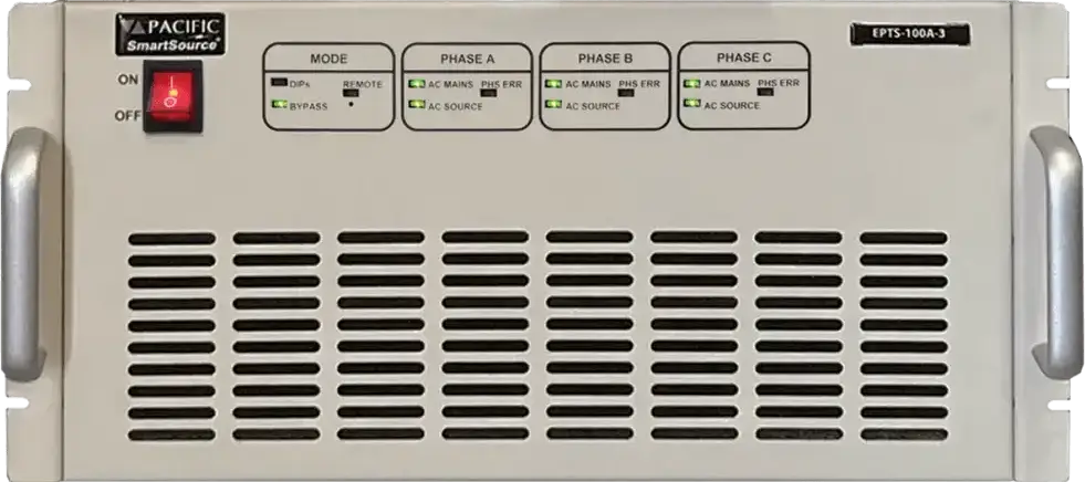
EPTS-3-75 Electronic Power Transfer Switch – Three Phase, 100A per phase

The transition times for voltage dips and interruptions is determined by the Solid State electronic switches that switch between the two AC voltage sources.  This requires synchronization of the programmable AC power source that provides the dips and interruption levels to the nominal voltage AC source, typically 230Vac and 50Hz or 120Vac and 60Hz provided by the local utility. This concept is illustrated in the figure below.

PPS-Electronic-Power-Transfer-Swith-EPTS-System-Diagram-1024x586.jpg
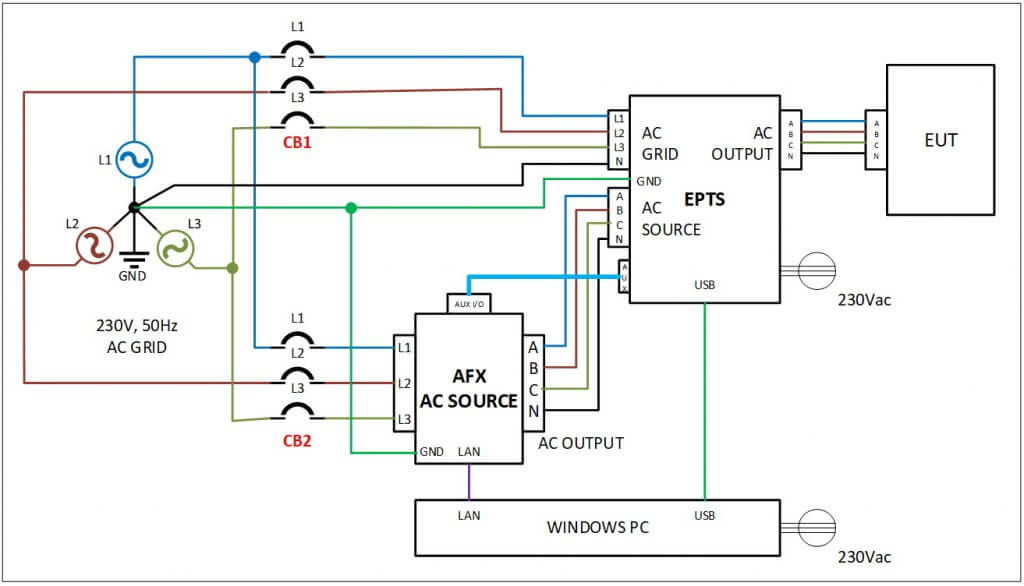
PPS Electronic Power Transfer Switch (EPTS) System Diagram

The resulting voltage transients at 90° and 270° where the voltage slew rates have to be fast enough to meet the < 5 µsec rise and fall times. For the case of 230Vac nominal voltage, the resulting voltage waveforms for the EPTS are shown in the two scope images below.

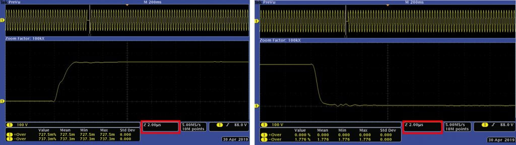
EPTS Voltage Rise and Fall Times

Summary

In order to fully meet the requirements of IEC 61000-4-11 clause 6.1.2 however, the use of an EPTS would be required. Clause 6.1.2 requires verification of rise and fall times at 90 and 270 deg with a 100 Ohm resistive load for a fully compliant dips/interrupt test generator.

This approach is particularly useful in Asia and Europe. EPTS units are available in single or three phase version and up to 100Arms per phase. See https://pacificpower.com/products/epts-option for available models. The EPTS units also alleviates the need to meet the peak inrush requirements for IEC61000-4-11 and IEC61000-4-34. See separate our Application note “IEC 61000-4-11 & 34 Testing and AC Source Peak Current”.

For USA applications, a second AC source or AC Generator is needed to test with 50Hz, 230VLN single or three phase nominal voltage.