Programmable AC power sources used for development and test applications convert locally available utility power to specific precision AC or DC output formats needed to test or control units under test. This is called “solid state power conversion” as active electronic circuitry is used rather than rotary converters or voltage only transformer. This has numerous advantages for test applications:
- Conversion of both voltage and frequency at the same time
- Galvanic isolation between the grid and unit under test as the power source output can be floated
- Available phase conversion between single, split or three phase grid to either single, split or three phase as needed
Regardless of the test objective, solid state power converters take utility power as input and convert to the desired output power voltage, frequency and phase configuration.
Single Phase AC Input
Single phase AC input configurations are by far the most convenient as any lab or factory floor will have single phase power outlets. In countries where 230Vac or 240Vac grid voltage is standard, this provides for reasonable available input power to support requirements of up to 3000W.
For countries like the US or Japan where AC line voltage is only 120Vac or 110Vac, far less power can be drawn for a standard AC outlet. A typical 120Vac outlet only supports 10A so best case, 1200VA is available. This ignores possible low line voltage conditions that may reduce input power further. There are 120V, 20A outlet versions available in the US but there are not very common and use a different pin orientation so standard modular line cord plugs won’t work with these.
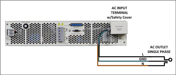 Figure 1: Single Phase Grid Connection
For power output requirements higher than 1000W in the US, a split phase 240Vac or three phase 208V will be needed.
Three Phase AC Input
Three phase power is typically used for higher power and industrial applications. Factory floors and power test labs typically have three phase outlets available. For office building, three phase power is used for lighting which is a big consumer of power so three phase power may be available in the building but three phase outlets may not.
There are three common three phase configurations available in the world:
- 208Vac three phase Wye Japan
- 208Vac three phase Wye US
- 400Vac three phase Wye Europe, Asia
- 480Vac three phase Delta US
Higher voltages may exist in some countries (Canada) and Delta/Wye transformer may be used to change from Delta to Wye or vice-versa.
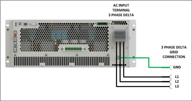 Figure 2: Three Phase Delta Grid Connection
Delta or Wye Input?
Not all higher power AC or DC power sources have the same three phase input configuration. Pay attention to the type of three phase voltage configuration supported by the power source you are considering. If the input configuration is a Delta, the power source can be used with either a Delta or a Wye grid configuration. The neutral connection is not needed when connecting to the grid.
If on the other hand the power source needs a neutral connection (Wye input supported only), they cannot be used with a Delta grid. These types of input design often are impacted when driving grossly unbalanced three phase loads as there can be a substantial amount of Neutral current flowing. The performing load unbalance compliance testing, try to avoid such power sources
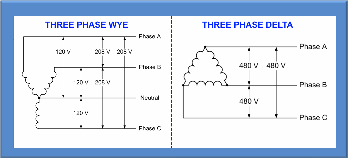 Figure 3: Three Phase WYE vs DELTA Configurations
Of course, equally important is paying attention to AC input voltage range. It has to match what is available at the location where the equipment will be used.
While power factor corrected single phase input power sources often have a wide AC input voltage range, three phase products typically do not as the wide input current range requirement associated with that would be difficult or costly to implement.
Some products however use AC input transformers which may support multiple voltage input transformer taps allowing re-strapping for different locales in the world. The drawback to this is that such power sources are typically quite a bit larger and heavier as a result.
AC Input Current
Input current requirements are determined by several factors for both Single or Three phase input configurations:
- Input voltage range
- Output power rating
- Power factor
- Efficiency
- Overload Operation
All these factors determine what the AC input VA will have to be to support maximum rated output power of the programmable source. For example, if we have a 2kVA source connected to a resistive load, the max. output power will be 2000W as well as 2000VA. Let’s assume the input specification is as follows
- AC Voltage Input range: 230Vac ± 10%
- Current: 15A
- Power Factor: 8
- Efficiency: 82%
Since the AC input voltage is 230V nominal, we have to allow for operation down to 230V * 0.9 = 207Vac worst case. Not all power grids in the world are stable and low line brownout conditions can be quite common.
To get the required 2000W output, the input power required from the grid will be determined by the following formula:
Pin = (Pout / PF ) / Eff
For our example, this equates to:
Pin = (2000) / 0.8 ) / 0.82 = 3048 VA
At a worst case low line input voltage of 207Vac, this will require 3048 / (230* 0.9) = 14.724 A.
For a three phase power source input, the relationship between required input power and current is calculated in a similar way but the actual current needs to be divided over three phase or by √3. Thus, a 10kVA input power requirement on a 3 phase 208V grid connection would result in
((10000 / (208*0.9)) / √3 = 30.84 A RMS per phase.
This illustrates the impact of both power factor and efficiency on AC input currents and associated facility breaker and input wire sizing. In this single phase input example, the 15A input current is generally available on standard 230Vac outlets in Europe and other countries. Once we need more than 2000W output power, we would either have to select a more efficient or better input power factor AC sources or consider using three phase input power. Let’s look at the two specifications that have the biggest impact on required AC input current, power factor and efficiency.
Inrush Current
While we covered required RMS input current to support full rated output power, we also need to pay attention to initial inrush current when a power source or power supply is first turned on. Since most input circuits consist of a bridge rectifier and bulk storage capacitor, initial current peaks may be high if the input capacitor is fully discharged. This may be true of power factor corrected input designs as well.
To prevent nuisance circuit breaker tripping due to excessive inrush currents, make sure the power source is equipped with a soft-start circuit. Such a circuit uses a current limiting resistor or thermistor to limit the peak inrush currents while the bulk storage capacitors on the DC bus charge up. Once charged, this resistor is either bypassed or remains in a low impedance state if a thermistor is used.
Pacific models with power ratings of 4500VA or higher all have soft-start circuits built-in. On lower power models, it is not always required but can be offered as an option.
Power Factor
Higher power factors can be obtained by selecting AC power sources with power factor correction. There are two methods commonly used:
- Passive PFC
- Active PFC
Passive PFC uses a line input inductor to compensate for any input inductance result in power factors that can be as high as 0.85. On three phase AC input designs, where the power factor correction will have to be done on each of the 3 phase lines separately, the cost of the PFC circuit can add up quickly.
Active PFC circuits however employ switching circuits that dynamically draw current so that the input waveform matches the desired sinusoidal waveform. These are often employed for high-performance power sources that are designed for precision and low noise. Active PFC is also used to provide high efficiency and works over a wide range of AC line voltages and loads.